CM108 Sound Fob Modifications for use with TxCR
This page is linked from How To - Build a High-Quality Full-Duplex AllStar Node for Under $150
Overview / Notes
In typical use as a PC sound card (without strong nearby RF fields) CM108 fobs have excellent (Hi-Fi/CD quality) stereo line out audio but the (unmodified) mic input has significant digital noise in the intended use with an electret mic. Removing bias resistor R6 fixes that at which point the mic input then can sound great with over 60dB SNR.
Most mods that people have been doing to these fobs are unnecessary. Various pages online say to remove the 3.5mm jacks and cut various traces but there's no need to do that. Doing so provides some extra small solder pads but the metal pads on the tops of the jacks already provide large solid areas to solder to. In less than an hour I can remove R6, add a transistor and resistor, add ferrite beads and bypass caps on all I/Os (ie. Rx & Tx audio, PTT, COS, and 5V lines in and out), separate the analog and digital grounds, and solder on the radio cables.
Some C-Media ICs including the CM108B and CM119B can run with or without an external quartz crystal. Fobs that do not have a quartz crystal should probably be avoided, as the sample timing may not be as precise. The B versions also have a pop filter for the mic input, which rolls off low-frequency response and could be an issue in apps doing CTCSS decode, but since the RX HT does that in this node the pop filter is probably a good feature to have. Also note that only C-Media or Syba fobs should be used. The CM108 fobs appear to have been made by C-Media themselves as evaluation boards, thus why they have a high build quality but no case or USB connector housing. Other fobs are not as well made or encapsulate the IC in a resin material preventing access to the pins.
C-Media notes that "Because USB Power has a 1KHz noise, it needs an RC Filter (10Ω and 10μF) on DVdd (pin 35) and AVdd (pins 29 & 34) to reduce this effect." C-Media CM108 and Syba CM119A fobs and most other URIs have pins 34 and 35 connected together. To install an RC filter requires cutting the trace between those 2 pins and replacing with a 10Ω resistor, then adding at least a 10μF capacitor from pin 34 to Ground. In my testing this makes a major improvement (8dB SNR increase in 1.5W full-duplex operation) with noise dropping from -36 to -42 dB, or from -45 to -47 dB w/6dB TX attenuation.
Many C-Media fobs now use the AH version of the IC. The CM108AH has significantly more Tx audio gain than the CM108B. In my tests so far the CM108AH fobs appear to have better noise performance than the CM108B's but I am still in the process of better quantifying that and I have not been able to get any answers from C-Media on these performance differences other than what's shown on their datasheets such as the frequency response differences. The B versions are stated as having a response of only 100-19K vs. 20-20K Hz for the AH version. My tests revealed that the B is 3dB down at 100Hz and 6dB down at 50Hz relative to the AH, a very gradual rolloff. For ASL purposes we only care about the ~67 Hz to 3.5KHz range, and frequencies below 100-200Hz are only of interest if ASL is doing CTCSS decode, which would generally only be done in repeaters, not in personal nodes. Even at 67Hz (lowest PL tone) the B response is only a few dB down from reference.
There is a similar fob made by Syba that uses a CM119A IC. These go for $10, which is still very cheap. The Syba fob has a small plastic case and a USB connector metal housing and is thus a good alternative.
HT speaker outputs can drive loads as low as 8Ω and for minimum chance of induced noise on the Rx Audio line the fob should present a load resistance somewhere in the range of 100Ω to a few KΩ. The existing 1.2KΩ resistor R7 on the fob helps with this somewhat as it goes to a small capacitor to ground, though for the lowest possible noise a ~100Ω termination resistor could be added on the fob.
Modifications
Modifying a ~$5 CM108 or CM119 Sound Fob can result in a significant cost savings, however this should not be attempted unless you have significant experience working with surface-mount electronics. Also note that in my experience the BH7NOR R1 or Repeater-Builder RIM-Lite-V2 interfaces provide at least several dB lower noise due to their having much more thorough RFI filtering. If it turns out your modified fob is too noisy you can always then upgrade to a better URI. Modifications are as follows:
- Remove resistor R6
- Attach a 2N3904 or other general purpose NPN transistor Emitter to Ground, attach a 4.7KΩ resistor between the transistor Base and Pin 13 on the CM1xx (PTT)
- (Optional for Hardware-COS) Attach the COS output from the RX RT85 to Pin 48 on the CM1xx. (Alternatively, the COS output can be converted to active-low by connecting it to a 4.7KΩ resistor which then connects to the Base of an NPN transistor, with the Emitter connected to Ground and the Collector to Pin 48 on the CM1xx. In this case set carrierfrom = usb in simpleusb.conf instead of carrierfrom = usbinvert.)
- For best RFI-resistance and lowest noise a ferrite bead and 100pF-1nF capacitor should be added to all I/O lines. See the schematic for the RIM-Lite-V2 for a good example of how this is done
- To further reduce RFI and 1KHz USB noise the analog and digital grounds should be separated. Cut the trace between pins 34 and 35 and replace with a 10Ω resistor, then add at least a 10μF capacitor from pin 34 to Ground
- Connect the radio cables as described in the Radio Interface Cables section
- Secure the cables to the fob using small zip ties or enclose the fob in clear heat-shrink tubing
Closeup of a CM108 Fob with Added PTT Output
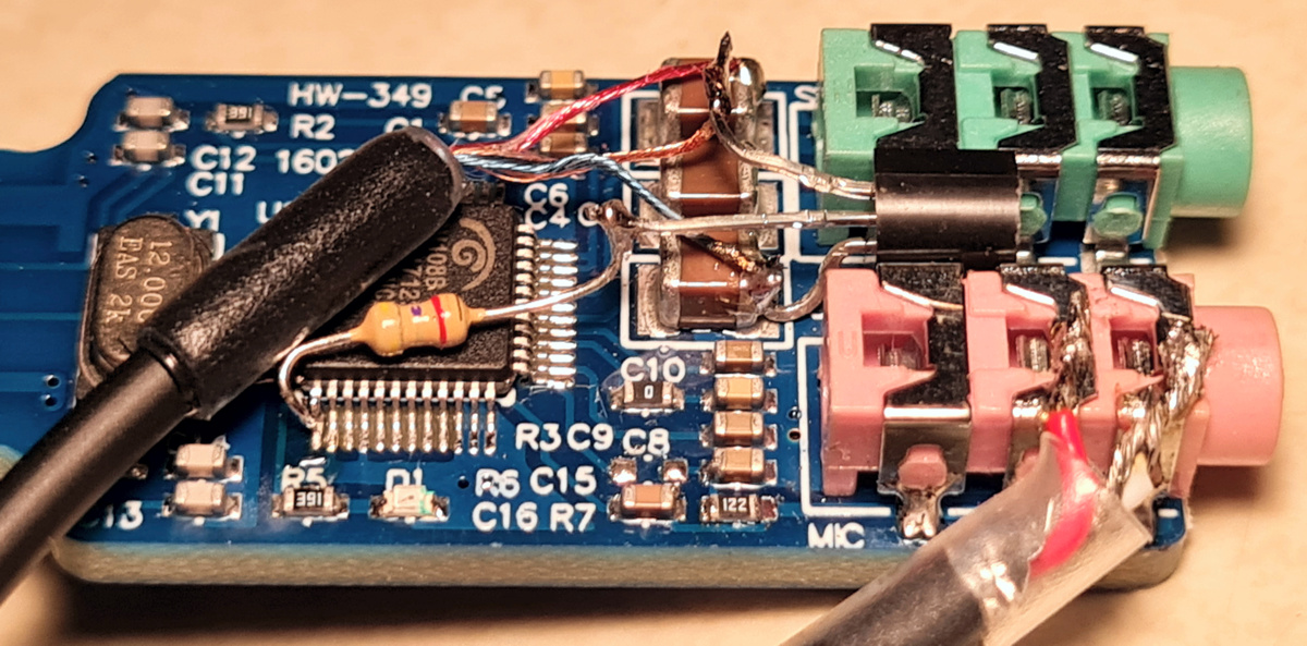
Note at the top middle there are 3 light brown capacitors in a row. The top 2 are on the Tx audio lines and the lower connects to ground. Thus the right side of the top one is a great place to connect the Tx Audio wire, and the right side of the bottom one is a great place to connect to Ground. Notes on the above image:
- A 2N3904 transistor fits perfectly between the 2 3.5mm jacks and its Emitter then connects to Ground on the right side of the light brown capacitor there
- The Base of the transistor then connects to a 4.7KΩ resistor which then goes to Pin 13 on the CM108
- TX HT 3.5mm cable connections:
3.5mm Ring: Tx Audio - connect to right side of top light brown capacitor
3.5mm Sleeve: PTT - connect to transistor Collector
3.5mm Tip: Not used - fold back wire and cover with a small piece of heat-shrink tubing
Note: Fob ground must be connected to the HT power supply ground - A K1 cable can optionally be used to the TX HT instead of a 3.5mm cable. K1 cable wiring:
Red: Tx Audio - connect to right side of top light brown capacitor
Gold: PTT - connect to transistor Collector
Blue: Ground - connect to right side of lower light brown capacitor
Green: Not used - fold back and cover with a small piece of heat-shrink tubing - The RX HT cable connects to the Mic Jack as shown. Note that some cables have red and white reversed. White is supposed to be channel A (Left) which is on the 3.5mm Tip. But many cables (such as the one above) instead have red connected to Tip. This then can go to Tip or Ring on the 3.5mm jack on the fob which are connected together since CM1xx mic inputs are mono. If you have modified the RX HT to have COS on the 2.5mm jack Ring, connect that wire to Pin 48 on the CM1xx
- Not shown: Additional ferrite beads and capacitors that should be added on all I/O lines, extra resistor and capacitor needed to separate the fob analog and digital grounds
An advantage to this approach is that the 3.5mm jacks on the fob are still intact and usable. This can be useful for test/debug purposes, and the node can also be used with a speaker-mic or headset with the radios off. However the speaker-mic/headset would probably need different audio level settings which would require some adjustments to the usbradio/simpleusb gain settings, and most have electret mic elements that require DC power to be provided on the mic audio line. It would be fairly easy to make a small interface board that did the necessary level conversions.